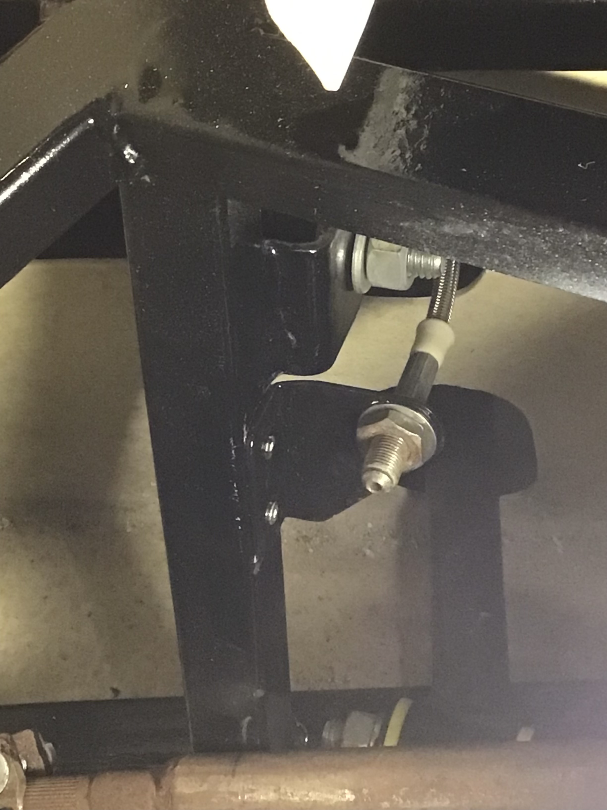
Having mocked up the handbrake cable routing rigorously, and drilled for the rivnut that would secure the handbrake fitting nearest to the hub on either side, I had a crisis of confidence. I had previously decided where the flexi-brake lines would terminate/mate to the rigid brake lines (and carefully photo’d the planned location), but I hadn’t actually committed to drilling the holes to allow the necessary brackets to be riveted in place. So all of the careful checking for binding/fouling through the full range of movement of the suspension (full droop and full bump) was replicated, then the necessary drilling carried out.


Rather than seal the holes at the point of rivnut installation with Sikaflex as i’d originally planed, I decided to instead drill all the necessary holes (for the rivets to hold the flexi brake lines, for the fixings to retain the handbrake cable, and for the fixings to hold the fuel tank straps), and then take the opportunity to repaint most of the rear end chassis rails, thereby ensuring that all bare metal had at least a touch of primer and top coat on it. So the same process was carried out with the handbrake cables, as for the flexi-brake lines, checking everything could move freely in bump and droop, before drilling the remaining holes needed for rivnuts.

At the same time as repainting the chassis rails I painted the flexi-brake line brackets. Cut from galvanized box section the brackets required an etch primer, but got the same top ‘Fortress’ gloss paint topcoat as the chassis.


Once the brake line brackets had been painted, and the rear end re-painted, I riveted the brackets in place permanently. To get access with the riveter it turned out I had to drop the lower wishbones out of their brackets, having thought I’d tightened those bolts for the last time months ago!


I then fitted the four rivnuts to hold the rubber lined p-clips which secure the handbrake cable. And then mocked up the routing for the hard brake lines, with a first stab at shaping the necessary lengths, having decided where to fit the t-piece which will split the single brake line which comes through the tunnel, to allow it to feed two rear calipers.

With the flexi-brake line setup looking like it’s mostly sorted I’ve been working on the handbrake arrangements. Once again, I am seeing the value of doing a full build up to a working car before painting the chassis, having again found something I now need to repaint…
The handbrake lever comes from the donor Sierra, and the cable is a genuine Sierra part, but the mounting arrangements are different, given the back of the car was somewhat further away in the OEM installation. I’d previously put in a backplate of 3mm steel, drilled to 10mm, at the top of the transmission tunnel; for the outer cable to terminate against. On arrival of the handbrake cable (suitably ended for disc brakes, rather than the drums on my donor) it was apparent that the inner cable would need shortening AND working out how to fit the cable overall would be easier if the backplate had a couple of slots, to allow the cable to be fed through without having to cut the inner first.
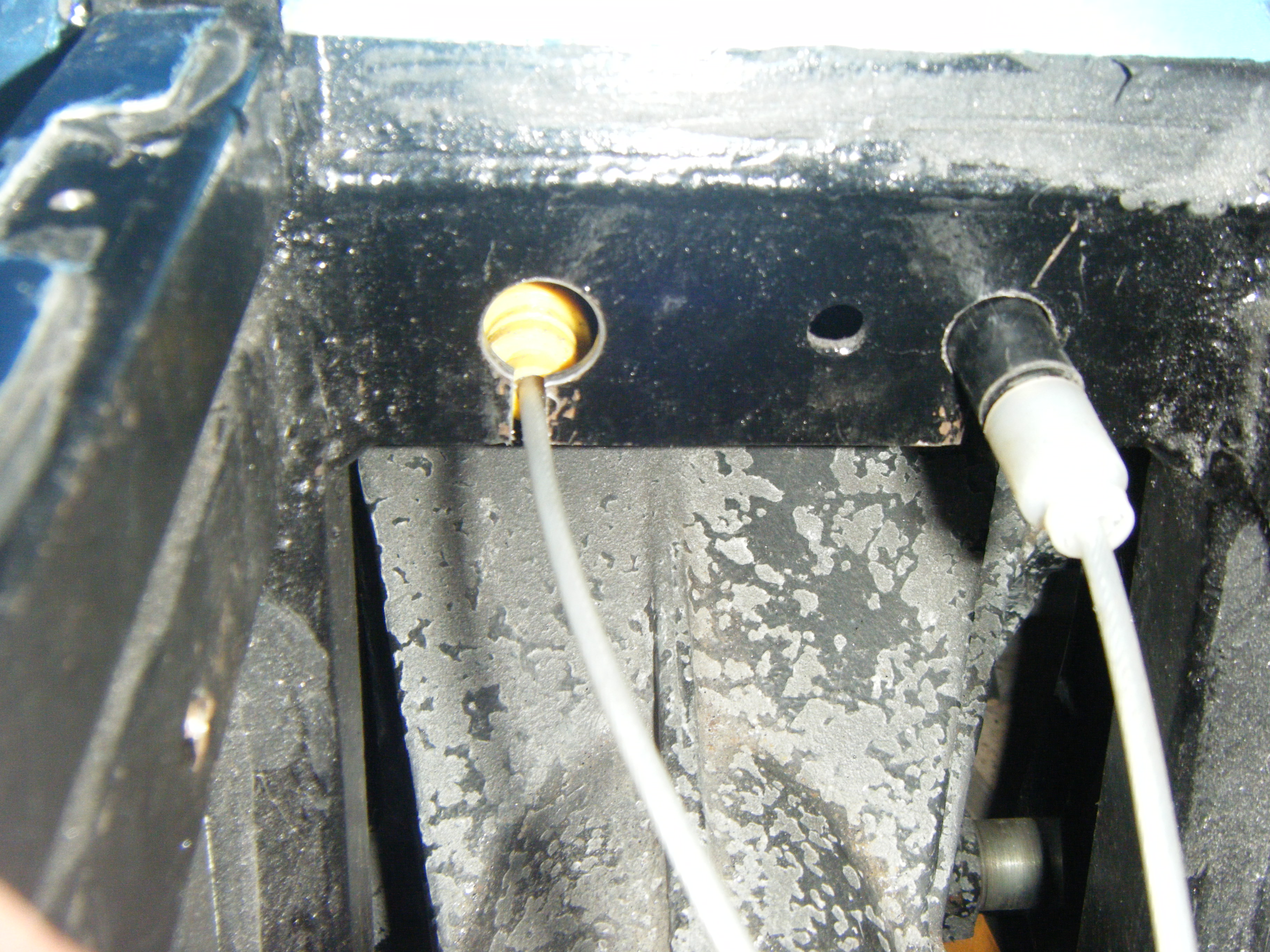
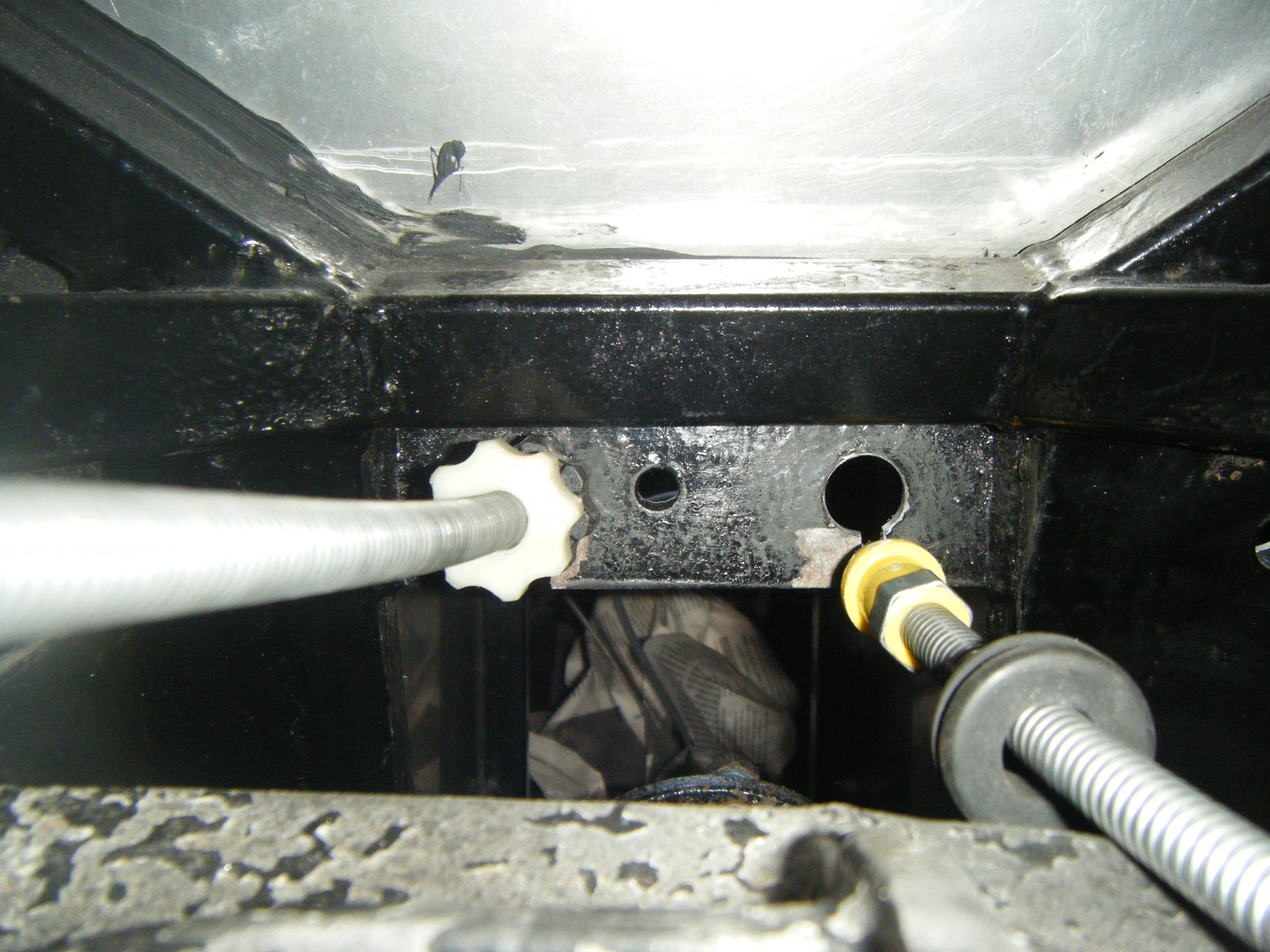
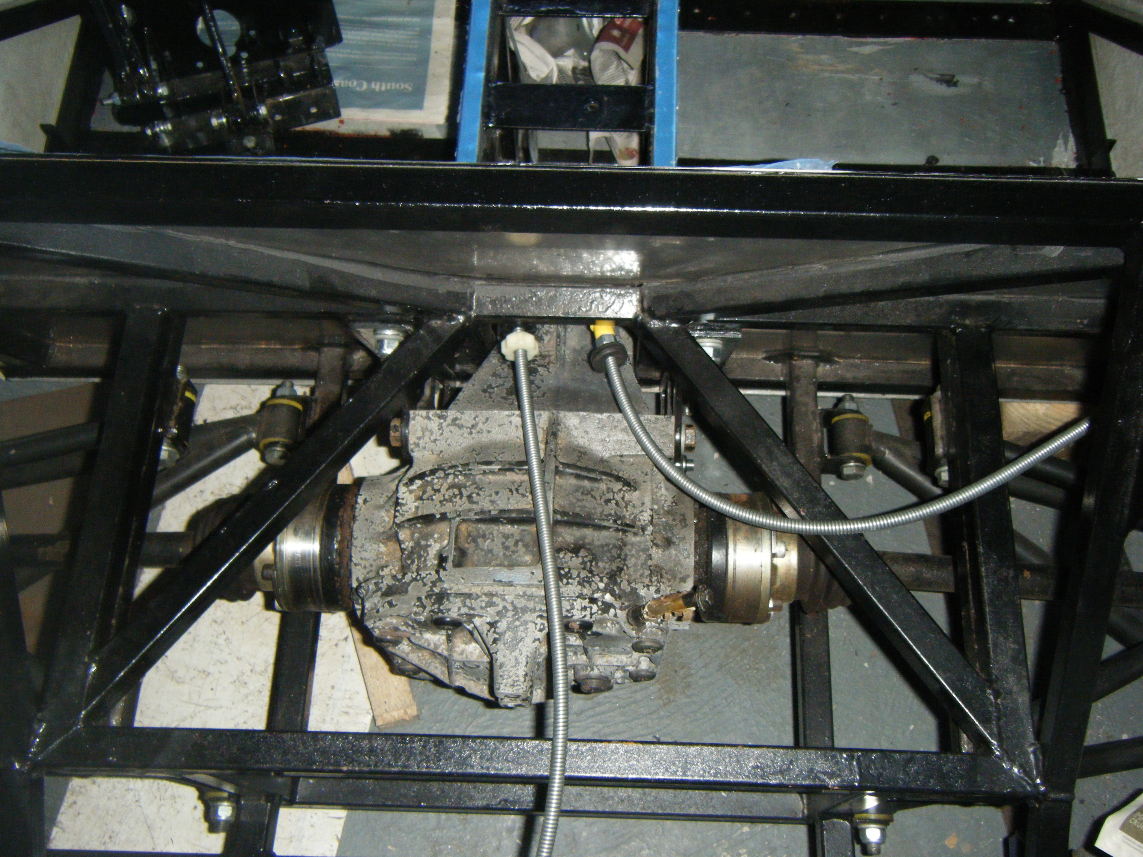
It was slotting the backplate (given where it is fitted, this was laborious and achieved by chain drilling at 3mm then filling out) that enabled me to discover that the 10mm holes needed drilling out, eventually to 15mm for the ‘adjuster’ side of the cable, and 16mm for the non-adjustable side (after enlarging first to 14.5mm and then 15mm). Unfortunately this necessitated dropping the diff out, a bit of an awkward job but one which yielded the opportunity to fit the correct length bolt through the bottom of the diff casing, allowing for a few threads to protrude from nyloc.
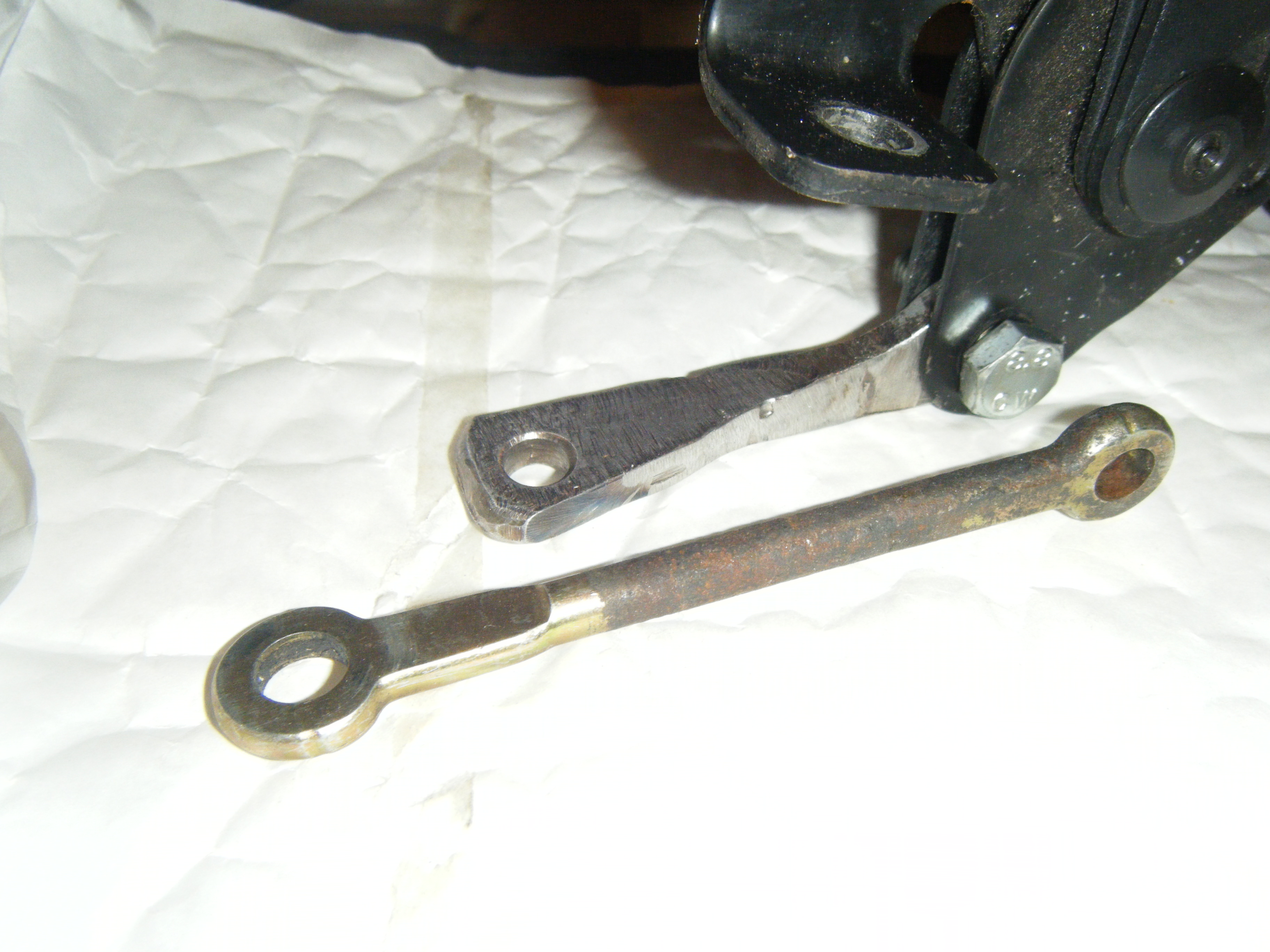
Having roughly run the cable through the backplate, it also became apparent that the link bar, between the handbrake lever and the crescent moon shaped ‘equaliser’, was too long, and wouldn’t allow enough space for the clamp that will inevitably be needed to rejoin the inner cable when it is shortened. As a solution I cut a couple of pieces of 5mm plate, with a hole drilled in one end, slotted them both at the other end so they could be wedged together at 90 degrees, and welded them into a single piece. Some time with the angle grinder has set me on the way to a neat replacement part, although it still needs a bit of finishing…

The final part of the jigsaw has been checking the cable routing will work with the full range of suspension movement. Having previously established that the cable exits the caliper without fouling the wheel (Brakes #4) I jacked the unsprung suspension all the way from full droop up to the bump stop, with no problems apparent. The final step will be drilling and fitting a couple of rivnuts into which to mount the rubber lined p-clips which will guide the outer cable, but that will wait until I’m bonding the side panels on, and have some spare Sikaflex with which to seal the rivnuts.

With the brake flexi line brackets remade, I had to open up the side panels a bit further. Once again, the sheet aluminim templates I had cut were useful. On this occasion I used the ‘circle’ that is created when using a holesaw, to outline a neatly radiused area below the existing suspension bracket hole; chain drilled; connected the holes up with an etching tool in my multi-tool; and finally smoothed out the edges with a mini-flap disc.

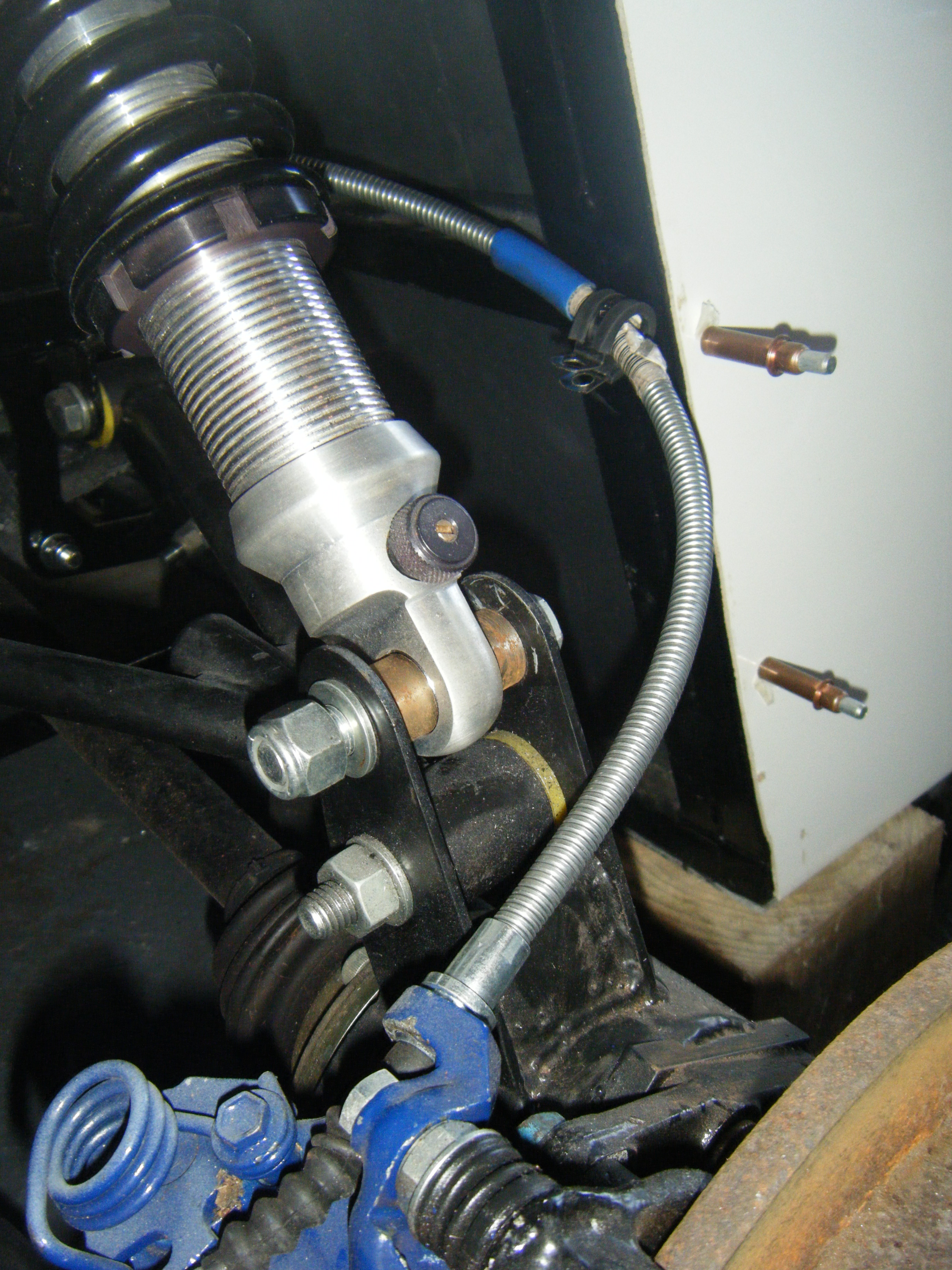
With a temporarily fitted brake line bracket the clearance across the range of suspension movement, and steering lock, looks to be good.

All of these edges will need to be trimmed with ‘U’ trim for the IVA, so i’ll try fitting some temporarily to make sure everything still moves freely before thinking the job is totally finished here…
I’ve decided to create separate brackets for the junction between the ‘hard’ brake lines (cupro-nickel) and the braided flexi-lines which will be bonded and rivetted onto the relevant chasis rails. The first prototype bracket was made from an offcut of the pub sign which yielded the floor panel. Later iterations have come from a piece of indeterminate metal box section (possibly galvanised steel), lifted from a skip several years ago.

Second left, the prototype. Centre, the front flexi bracket (the two large holes allowed for different brake line positions to be trialled), Right, the brackets for the rear brake lines. Far left, the original material (I cut some spare blanks incase anything needed to be re-thought).
In situ, the brackets at the front seemed to be heading in the right direction.

I’ve also re-made the brake reservoir mount. Efforts to swage some holes in the original version were reasonably successful but left it looking pretty agricultural. Mk2 reservoir mount is made of 2mm rather than 1mm alu sheet, and is rather stiffer without swaging.

With the rollhoop welded, I can now move towards fitting the GRP side panels in place permanently. Since the original chassis painting sessions six years ago, there have been plenty of scuffs and scrape, in both the engine bay and the ‘cockpit’ and so some touching up was in order. In addition, I bit took the opportunity to cut off the front brake flexi brackets. As i’d established they were too close to the wishbone bracket and the flexi’s wouldn’t clear the metalwork sufficiently, they need re-thinking.
Having not been massively impressed by the POR-15 paint I used originally, I’ve ended up with a mixed approach to re-painting. The relevant parts of the engine bay were oversprayed with etch primer (where i’d gone back to bare metal) and everything was recoated with the one remaining can of POR-15 Blackcote. The surface finish remains a bit lumpy in places.
In the cockpit I wanted to improve the quality of the finish, so rubbed back everything that would be visible to a smooth surface, then primed with red oxide (two coats) and top coated with B&Q own brand ‘Fortress’ metal paint (three coats, flatted back between coats one and two), all by brush. The end result, despite being brushed, is a much smoother looking finish, although it took the best part of 3 weeks just to do the cockpit, given the need to leave enough time for coats to cure, and wait for suitable weather that co-incided with weekends… Overall the re-painting, from first prepping to finishing paint has taken 8 weeks…


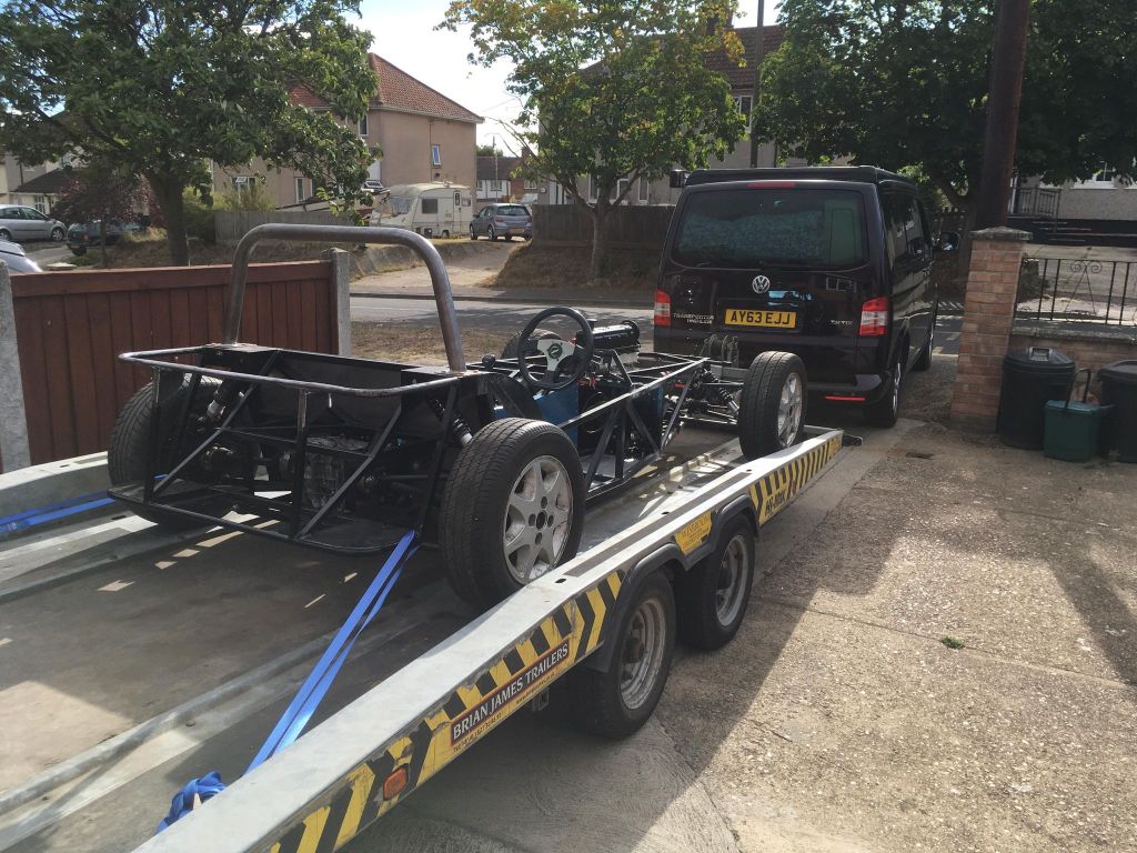
Having resolved to get someone else to weld up my rollbar back in March, and making some initial enquiries, I finally made moves to get things sorted. I ended up using a local engineering firm, who also hire out trailers (and indeed provided the trailer when I first collected my project way back in 2012). I’d need to check the photos, but I suspect it may have even been the same trailer which I used to ferry my rolling chassis up to their workshop, and back again, about a week later.
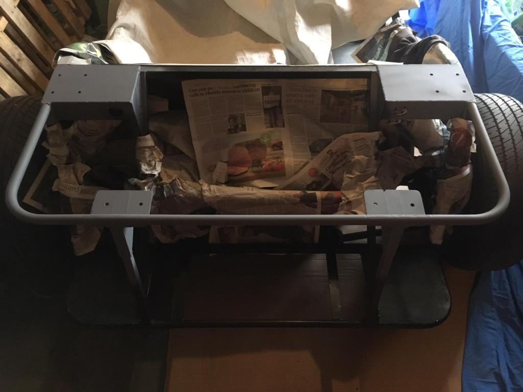
To keep things simple I stripped the chassis as much as I could, and cleaned up the rollhoop, stays and all the rear framework, both as prep for the welding and in anticipation of the repainting that it all needed once the hot work was over.

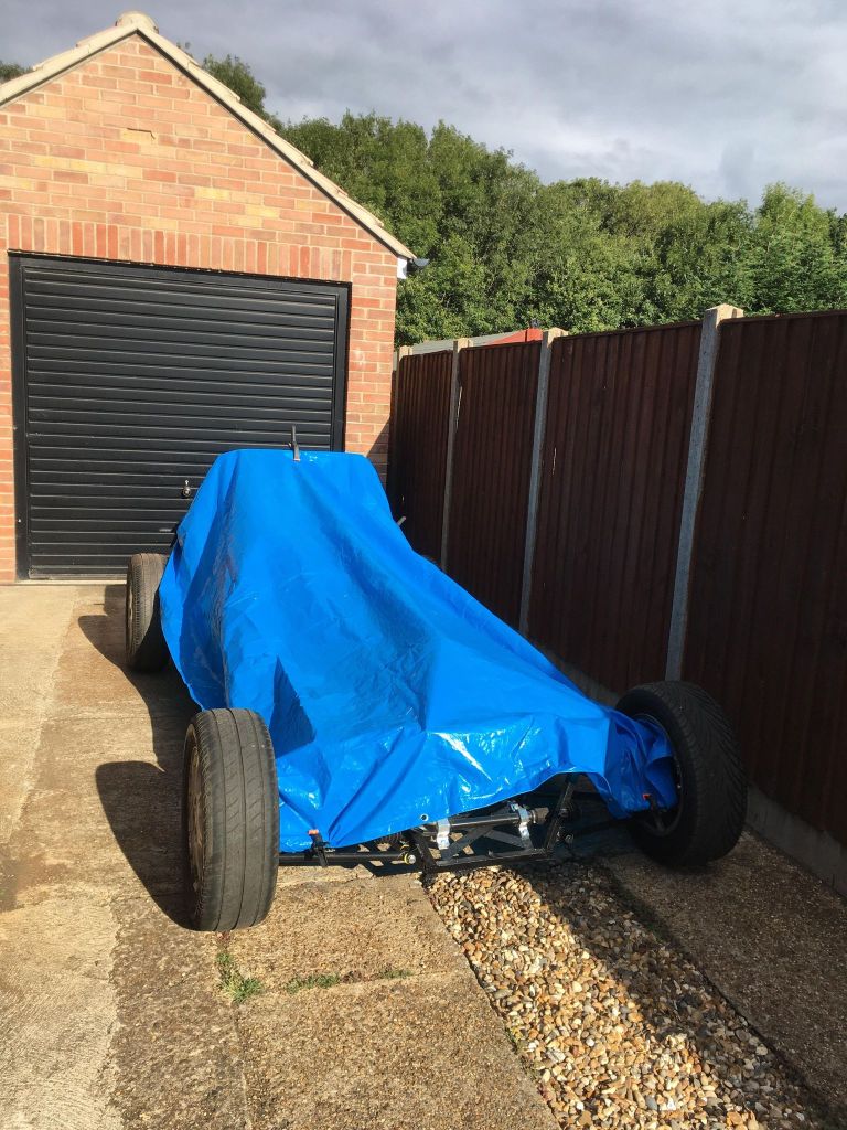
Thanks to tempermental weather I did this in the early hours one morning, then left it under cover ready for collection.
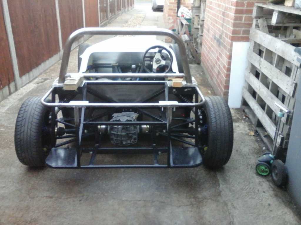
A few hours later, a bit of help from multiple generations, and off the car went..

And just over a week later it was back, with everything welded up.
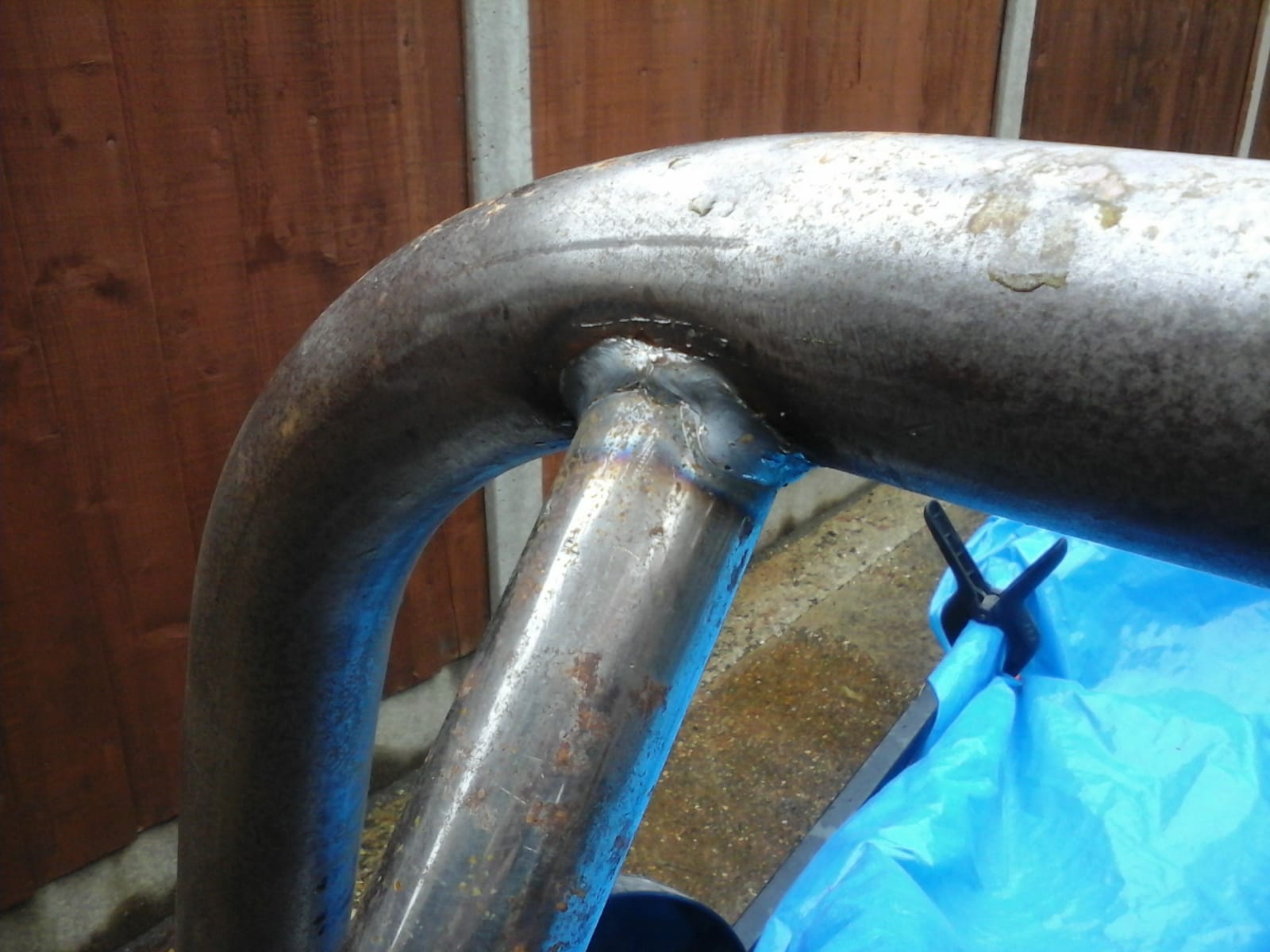
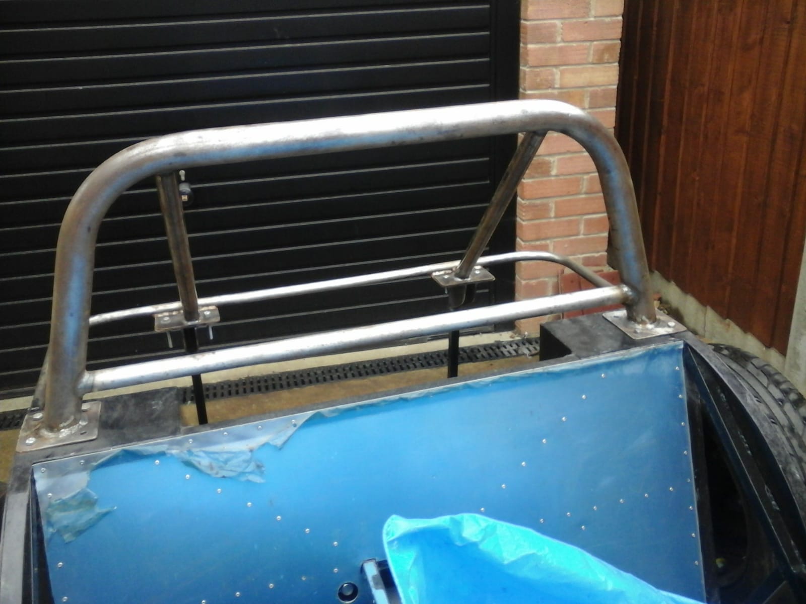

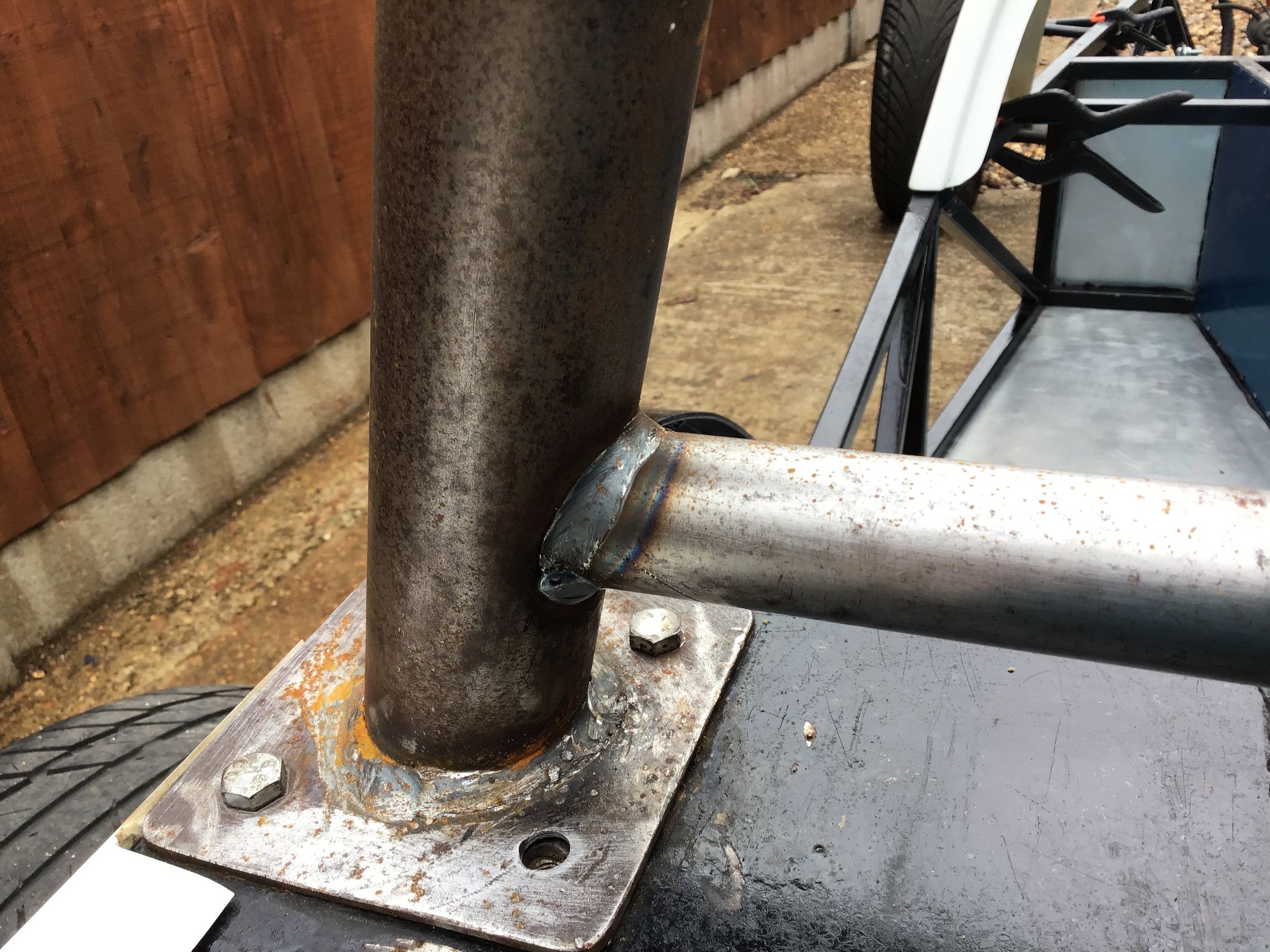

And finally, repainting the rear framework is well underway. The rollbar will be primed too, but final paint for that will have to wait until i’ve lined everything up for the upper harness mounts, drilled the cross bar to take some threaded crush tubes and the whole lot has been back to the fabricators for the welding…
A common theme throughout this build, clearly shown through my efforts to repurpose and use the Lanica/Fiat brake proportioning valve, is how to take an OEM part from one place, and deploy it in a new setting.
Thankfully I don’t have to worry about how to incorporate a pre-designed headlight into a new front end, or design a bodyshell around a windscreen that I must use, but I do need to include lots of running gear that was supposed to be in something else…
By choice i’ve ditched the Sierra brake master cylinder, and replaced it with the equivalent from a Mk1 Fiesta (should be smaller bore and apparently gives better pedal feel).
For ease of wiring and the inevitable cost-saving drive, i’m reusing the brake fluid reservoir from the Sierra but because I want to keep it orientated as it was in the Sierra (the top of the tank horizontal) I need to compensate for the fact that the master brake cylinder in the Sierra was angled upwards, and the Fiesta master cylinder is now sitting dead flat AND slightly recessed into the bulkhead.
Solution: remote mount the brake reservoir, using a simple bracket folded from aluminium, some low-pressure brake fluid hose and push-fit hose tails from (warning, third OEM manufacturer in almost as many paragraphs) a pre-1972 VW Beetle. I may cut a couple of holes in the sides of the brackets to allow access, but only if I can manage to swage them sufficiently by hand to put some strength back in…


Also, the bracket for the brake proportioning valve is now primed and ready for final paint.

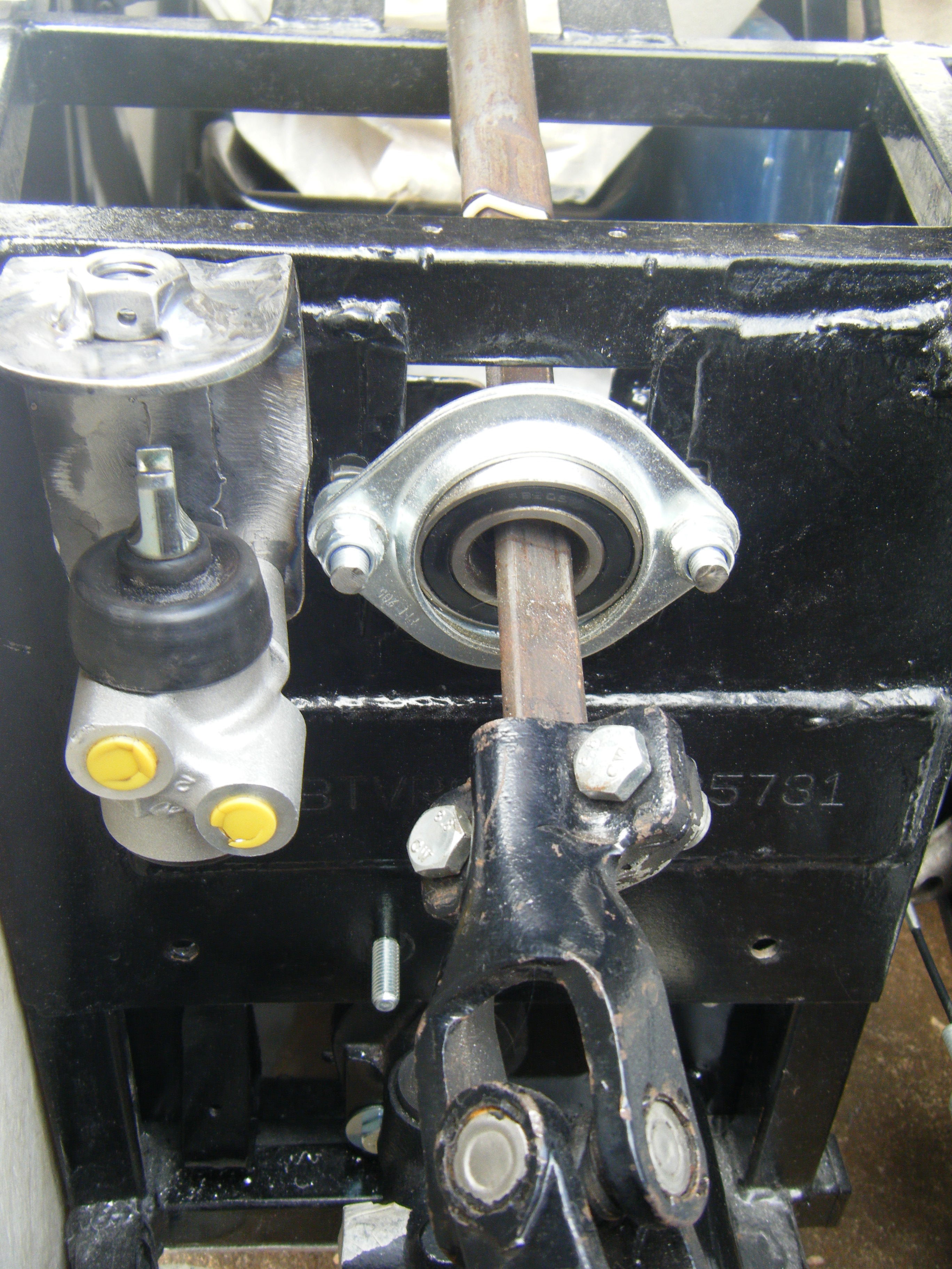
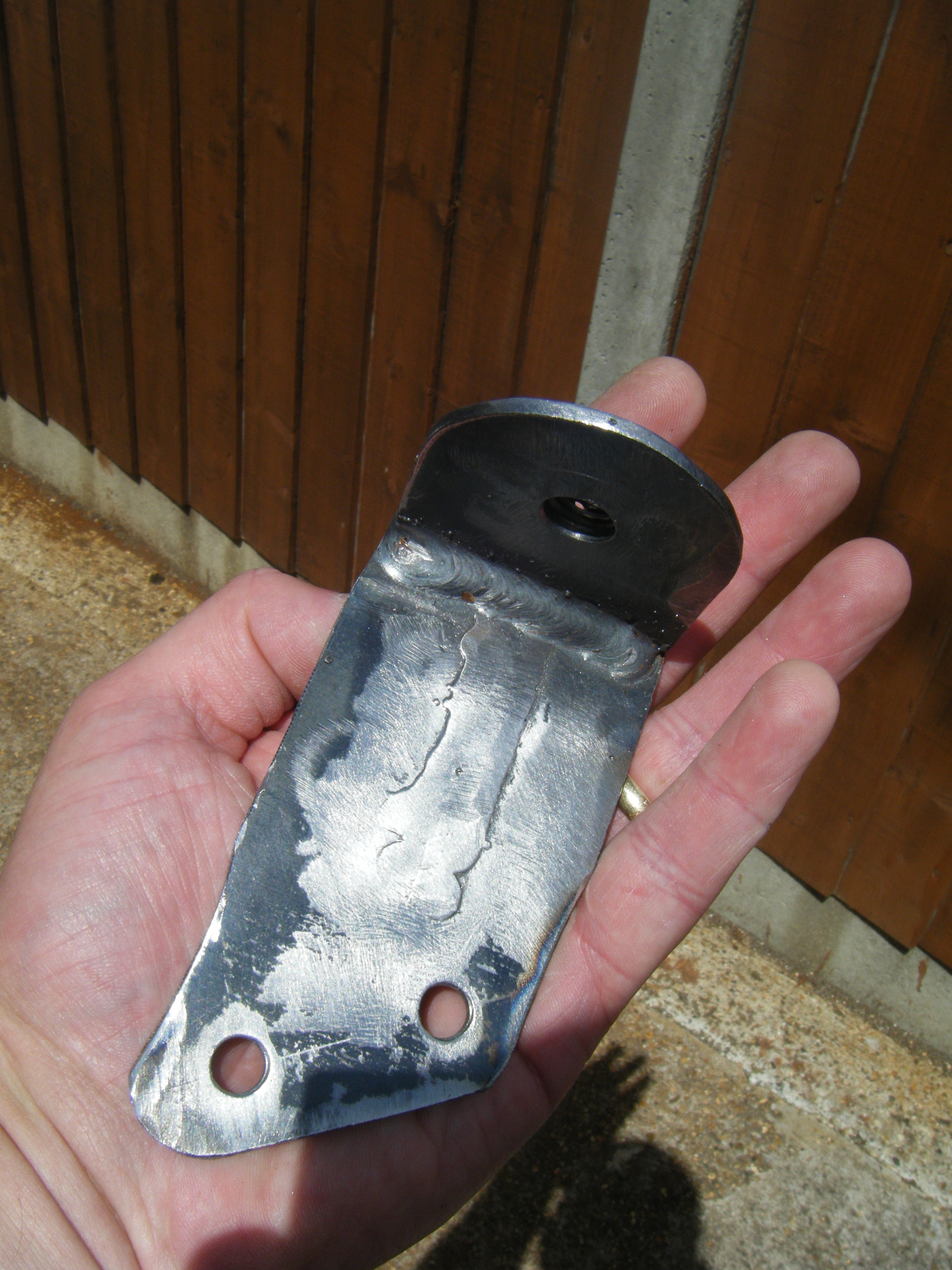
The bracket for the brake proportioning valve is now completed, and the mounting holes drilled. It is a fairly close fit next to the steering column bearing, so the bracket for the brake valve had to be trimmed down a little. As well as the two mounting holes that go through the bracket and into the brake valve body, I’ve added a third fixing point which I hope will stop any flexing and keep the bracket fully aligned.
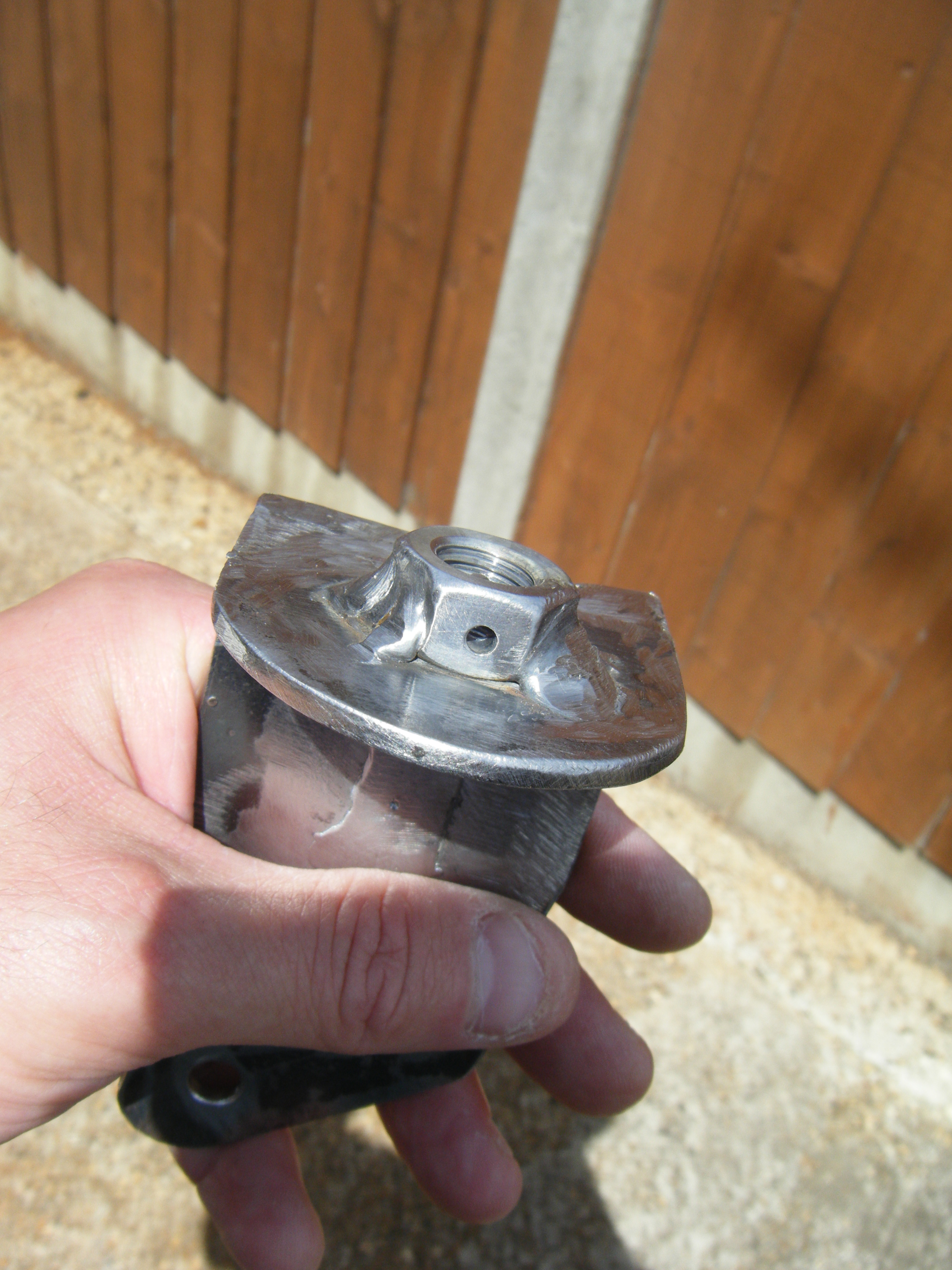
I’ve welded an M12 nut onto the top of the bracket, and drilled through at 3mm in preparation for fitting a roll-pin into a suitably positioned bolt once the valve setting is determined.
As the valve has blind holes for mounting i’ve chopped of a couple of lengths of M8 threaded rod to create a pair of studs, the third fixing point will be with a straightforward nut/bolt. Now it just needs a coat of paint and the next job wil be running some brake lines.
Two steps forward, one step back. Having decided that i’ll put the Lancia (ahem – Fiat) brake valve on the front bulkhead; I made a bracket, but wasn’t happy with it. The first version would have done the job, but looks very agricultural and – after I drilled a couple of holes in it – a bit like a cheese grater.


So brake proportioning value mk2 is now in production, and will be a more lightly built, closely fitted, affair.


The final component for the brake system arrived a few weeks ago. Although it’s commonly referered to as a ‘Fiat Uno’ brake proportioning valve the eBay listing I used to buy it also noted that the part was used in other cars, so for added glamour I’ll note that it’s also a Lancia brake valve.
I had hoped to be able to tuck it away neatly, low down in the engine bay, but I think I’ll end up with it mounted high on the bulkhead next to the steering column bearing.


I have started making a suitably beefy bracket that will sit around it and allow me to position an M12 bolt directly above the valve – so I can preadjust the amount of brake bias it allows, before welding eveything up before it goes off to the IVA test. I’m unclear whether this will prove allowable for the test, but it seems a better solution than using an inline valve which simply applies a preset pressure reduction (which is the other obvious ‘non-adjustable’ option)…
